A digital twin before the first screw
MK-II now exists as a 1:1 3D twin in Mission Control: head, three-axis neck and base with all 24 parts. Every move can be tested before the hardware arrives.
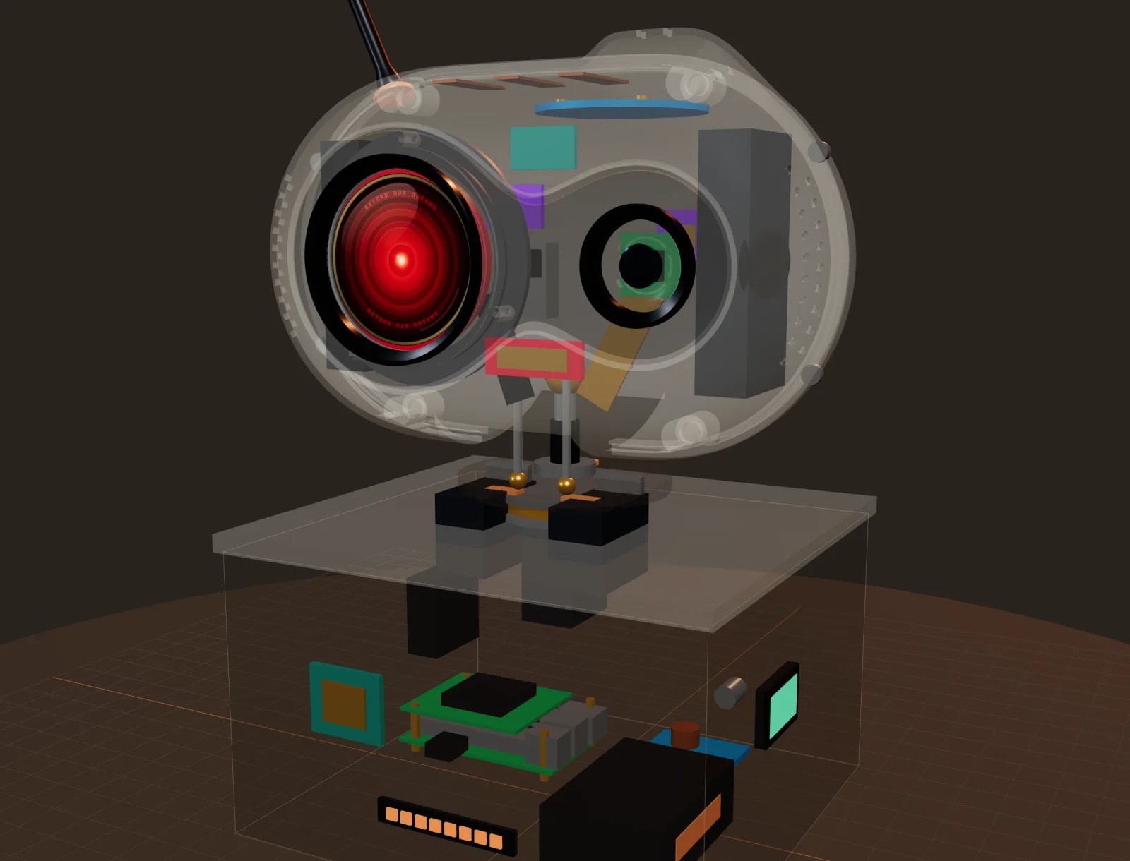
The parts are still in the post. BOB’s body already moves anyway — on screen.
With Mission Control v2.9.14a there’s a new 3D Model & Motion Lab: a one-to-one twin of MK-II, built from the same CAD data we’ll print from.
What the twin shows
- The head with its real shell, the round eye display and the camera.
- A three-axis neck: three servos let the head turn, nod and tilt — the first two to follow whoever is talking, the third for the curious head-tilt every good robot needs.
- A wooden base that holds the computer and power.
- All 24 hardware parts at their real positions. Switch to semi-transparent and you can see where every board, sensor and cable sits.
Why bother
Because finding a collision in a 3D model costs a click; finding it in printed plastic costs a weekend. The 3D work has already turned up a few of those — like how little room there is for the microphone array under the sensor dome.
It’s also the control panel of the future: sliders for turn, nod and tilt, presets for motion patterns, and the eye’s states and moods — all of it ready to send to the real robot the moment it comes online.
And the eye got its final name in the process: the BOB Eye.
Follow the build: all entries · RSS feed